Faridabad, Haryana
- GST NO. : 06NEKPS5012F1ZA
Rubber Testing Equipment
| Business Type | Manufacturer, Exporter, Supplier, Trader |
| Condition | New |
| Automatic Grade | Automatic |
| used | industrial |
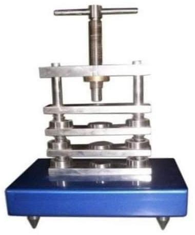
Compression set tests is intended to measure the ability of rubber compounds to retain elastic properties after prolonged action of a known compressive stress under static loading.
| Business Type | Manufacturer, Exporter, Supplier |
| Automatic Grade | Automatic |
| Application | Industrial, Residential |
| Country of Origin | India |
This device is specially designed for testing laboratories with high accuracy and foolproof results.
| Business Type | Manufacturer, Exporter, Supplier |
| Country of Origin | India |
| Digital dials | 0 to 10 mm X 0.001 mm least count or LVDT |
| Load cell | 1500 N |
| Motor | ½ hp 3 phase induction motor |
| Power requirements | 500 W, 220 VAC single phases |
| Related Standard | Astm F 36 |
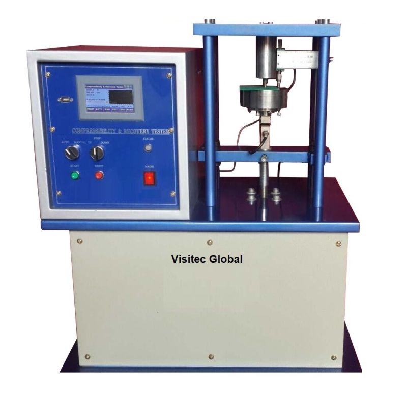
Our Compressibility and Recovery Tester of Gasket Material Consist of an Anvil- A hardened and ground surface on which the sample is placed. There are a set of steel cylindrical shape penetrators of specified sizes and shape according to the material test (as per Table-1). There are two dials also mounted on the anvil for the measurement of the thickness of the test specimen at the time of preloading and the total load. There are two digital dials so that by taking the average value you can measure the accurate thickness. There is the software in the load monitor for the application of preload and major load for the specified period after that buzzer give the indication to note the dial gauge reading. Preload – A preload which shall include the weight of the penetrator itself and added weight of the penetrator itself and added weights to give the value specified within ± 1%. Preloads for various types of gasket materials are as shown in Table 1, unless otherwise specified.
There is a selector switch on the control panel for the setting of load conditions as given below.
- Mode 1= pre-load 22.2 N & total load 1112 N
- Mode 2= pre-load 4.4 N & total load 222 N
- Mode 3= pre-load 4.4 N & total load 445 N
- Mode 4= pre-load 4.4 N & total load 356 N
There are two process of movement of the penetrator that is manual and other is auto. For testing purpose as per modes always use auto mode and for the movement of the penetrator always use manual. In manual mode for up and down movement first of all press the rotary switch for the up or down position and than in manual mode. And for AUTO mode switch off the digital monitor then select the mode and change the penetrator as per requirements then switch on the digital monitor. For testing place the test specimen on the anvil and then press the push to test switch.
All the parts are either painted/powder coating chrome plating for corrosion resistance long life.
| Business Type | Manufacturer, Exporter, Supplier |
| Automatic Grade | Automatic |
| Power | 5-10kw |
| Feature | Zero, Peak, Over Load, Over Travel Safety, Auto Reverse. |
| Country of Origin | India |
| Range | 500 Kg |
| Least count | 0.1 kg |
| Elongations | 25 to 900mm |
| Traverse Speed | Variable speed 50 to 500mm/min |
| Motor | 1 Hp, 1425 rpm, Induction motor |
| Power required | 220 VAC, 50Hz, 1000w, single phase |
| Unit Changing | N, Kn, Kg, G |
| Control | Up, Down, Stop |
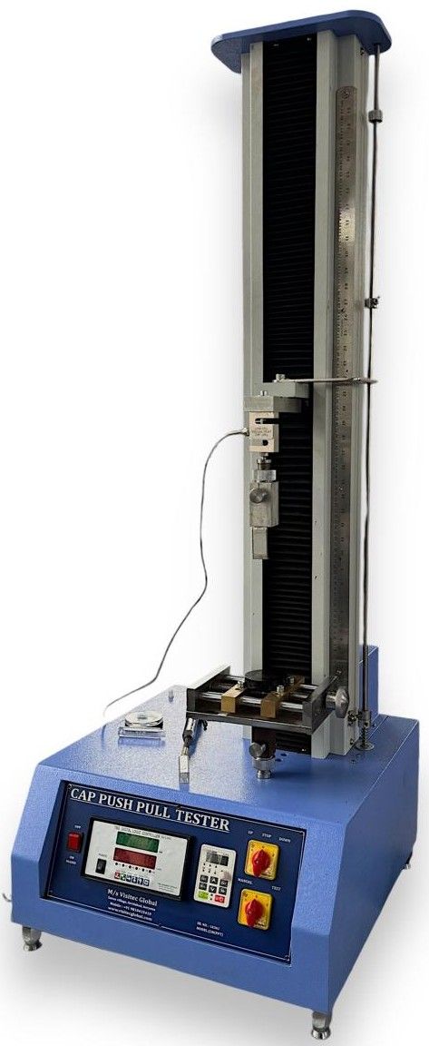
Tensile strength and elongation are the two prime characteristics of most of the raw materials, whether they are metals: or non-metals: such as foam, rubber, textiles, plastic, paper: or finished products such as rods, wires, ropes, yarns, belts etcetera. These properties very often play the major role in determining the suitability of any raw material for any specific application. It is therefore, of utmost importance to determine these characteristics accurately, conveniently, and quickly.
Tensile Testing Machine provides a relatively inexpensive way for determining the tensile strength and elongation of variety of raw materials such as rubber, leather, fabric, plastics, Belts, wires etcetera. They are based on constant rate of traverse principle in which one end of the test specimen is held in a stationary grip, while the other end is made to move at a known fixed speed with the help of motor, gearbox and screw arrangement. The load exerted on the stationary grip is sensed by a load cell and indicated by a digital load indicator. The controller is microprocessor based and has the facility of over load protection, peak hold and auto calibration. The load directly indicated in kilograms or Newton.
The elongation of the test specimen is measured on a digital indicator fixed on the frame of the tester, which indicates the distance between the grips. The frame of the tester fabricated from heavy mild steel sections to give the required rigidity and strength. Various built in safety arrangements such as over travel protection are provided.
The tester is finished in metallic painting and bright chrome| zinc plating to give the apparatus a corrosion resistant finish. It is supplied complied which electrical. Which include micro-, switches, Push buttons, and contactors for safe and convenient operation.
| Business Type | Manufacturer, Exporter, Supplier |
| Country of Origin | India |
| Frequency | 50 Hz |
| Material | Mild Steel |
| Dimensions of the specimen mm | 16mm diameter with minimum height of 6 |
| Dimensions of rotating drum | 150 mm diameter with x about 460 mm long |
| Speed of rotation of drum | 40 rpm |
| Lateral movement of test specimen holder | 4.2 mm per revolution of drum |
| Rotation of test specimen | 1 revolution per 50 revolutions of drum |
| Load on test specimen | 5/10N |
| Total length of abrasion run | 40 meters (about 84 revolutions) |
| Related Standard | ISO: 4649 – 1985,ASTM D5963, IS: 3400 (Part- III) - 1987 |
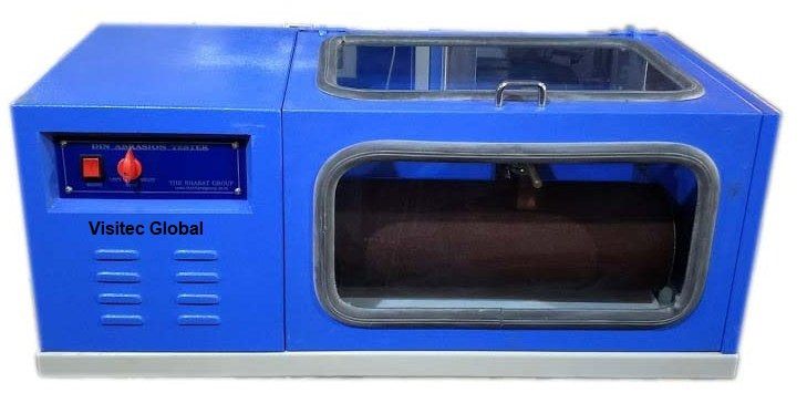
In Din method of determine abrasion resistance of vulcanized natural or synthetic, a cylindrical rubber test specimen is abraded against an abrasive surface mounted on a rotating cylindrical drum in such a manner that abrasion takes place on one of the flat ends of the test specimen which is held against the abrasive surface under a specified load while being traversed across it. The ratio of the volume loss of a standard rubber to the volume loss of the test rubber measured under the same conditions, expressed as a percentage, gives the abrasion resistance index of the rubber under test.
Din Abrasion Tester is designed to determine abrasion resistance index of natural and synthetic rubber in accordance with the above principle. It consists of test specimen holder with a cylindrical opening adjustable between 15.5 to 16.3 mm to clamp the test specimen with an arrangement to adjust the length of test specimen protruding out. The holder is mounted by a screw mechanism along a length of a rotating drum on which the abrasive cloth is fixed. The movement to the screw mechanism and drum is given by an electric motor, gearbox and chain mechanism to give the specified speed of rotation to the drum and the specified lateral movement to the test specimen holder. The swivel arm and test specimen holder are so disposed that the test specimen is pressed against the drum under the specified load with its centre axis at an inclination of 3 degree to the perpendicular in the direction of rotation and placed above the longitudinal axis of drum. A rack and pinion arrangement to rotate the test specimen about its axis during the test (whenever desired) is also provided.
The abrasive cloth is firmly fixed to the drum using a suitable peel able adhesive with the ends of the abrasive cloth butt jointed together. The equipment is provided with limit switches which, in addition of giving over travel safety to the movement of test holder by preventing the lower edge of the test specimen holder to touch the abrasive cloth.
The equipment is built on rigid steel base and finished in grey metallic and bright chrome / zinc plating to give it a corrosion resistant finish. Moulding die, rotary type cutting die(hollow drill) for preparing test specimens and extra abrasive cloth are available as optional accessories.
| Business Type | Manufacturer, Exporter, Supplier |
| Display Type | Digital |
| Country of Origin | India |
| Phase | single |
| Operating Current | Single Phase |
| Distance between supports | 100 mm |
| Temperature controller | 0 – 150º C X 1º C |
| Measurement of deflection | Dial micrometer of range 0 – 10 X 0.01 mm |
| Loadings | By dead weight to give loads from 100 gm to 1600 gm in Step of 10 gm. |
| Related Standard | Astm D – 1525 and Astm D – 648 |
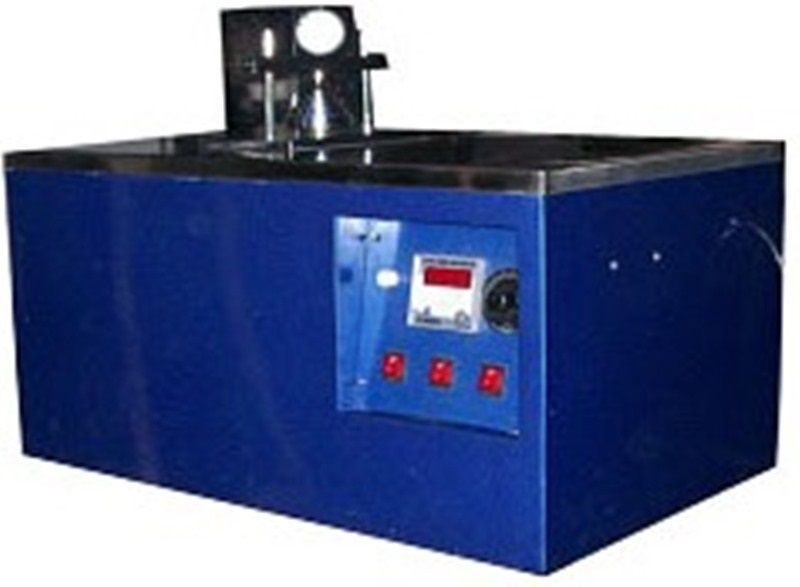
The Apparatus for Temperature of Deflection under Load consists of a specimen support, an immersion bath, a set of weights under deflection –measuring device.The specimen support consists of a two parallel metal supports having rounded edges fixed at a specified distance on an aluminium frame. Load is applied on the test specimen midway between two supports. This block is fitted to the lower end of the vertical rod, which is guided inside a metallic sleeve and is constrained to move without rotating along a vertical axis. The upper end of the vertical rod carries a load carrying plate on which loading weight can be placed to load the test specimen. All the parts are made of aluminium having same co-efficient of linear expansion.
The immersion bath consists of a double walled reservoir having the inner walls made from Stainless Steel sheet and outer walls made of mils steel sheet. The space in between the walls is filled with glass wool insulation. The liquid in the bath is heated by means of an immersion heater and the rate of rise of temperature controlled with the help of an electronic voltage regulator. A digital temperature controller is provided to restrict the maximum temperature of the bath.
The deflection of the specimen is measured with the help of dial gauge.
| Business Type | Manufacturer, Exporter, Supplier |
| Country of Origin | India |
| Condition | New |
| Brand Name | Visitec Global |
| Automatic Grade | Automatic |
| Features | Efficient, Easy To Use, Reliable |
| Other Relevant Characteristics | Testing Equipment |
| Number Of Flower | Rheometers |
| Payment Terms | T/T |
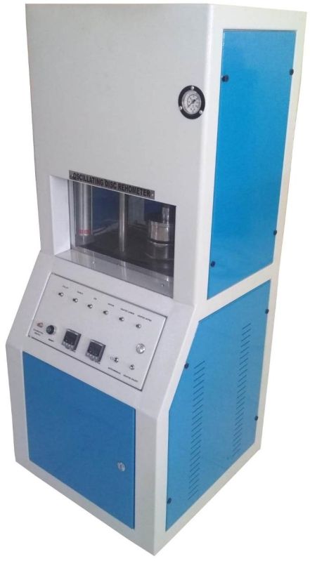
Our Oscillating Disc Rheometer is an efficient, easy to use and reliable testing equipment.
| Business Type | Manufacturer, Exporter, Supplier |
| Material | Stainless Steel |
| Finishing | Polished |
| Driven Type | Electric |
| Operating Type | Automatic |
| Usage | Hardness Testing |
| Display Type | Analog |
| Structure | Vertical |
| Country of Origin | India |
| Business Type | Manufacturer, Exporter, Supplier |
| Driven Type | Electric |
| Power | 1-3 Kw |
| Voltage | 220V |
| Country of Origin | India |
| Minor Force | 30.6+/- 2gm |
| Major force | 550.5+/-1gm |
| Radio us of indenter | 1.25mm |
| Dial gauge | 0 – 10 X 0.01mm (Digital or Analogue) |
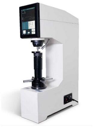
The hardness is obtained by the difference in penetration depth of a specified dimension ball under two conditions of contact with the rubber.
a) with a small initial force
b) with a much large final force
The differential penetration is taken at a specified time and converted to a hardness scale value.
The IRHD Tester made a vertical plunger. The lower side of the plunger has an indenter. The lower shape of the indenter is ball type of specified dimension. The upper sides of the plunger have a good eclectic conductive tip. The weight of the plunger and fitting attached to it is the minor force. A big brass weight is the major force of the specified weight. A dial gauge is attached to the instrument for the measurement of the penetration depth of the indenter to the rubber. An electricity operated buzzer, for gently vibrating the apparatus to overcome the slight friction is mounted under the cover of the instrument.
The tester is finished in NC based painting and bright chrome plating to give it a corrosion resistance finish.
RELATED STANDARD
ASTM D 1415 – 81 –Rubber property – International Hardness
| Business Type | Manufacturer, Exporter, Supplier |
| Load Range | 0 to 100 kg X 10 gm. |
| Lever Ratio | 1:5 |
| Curvatures of Toe Pieces | 25, 30, 35, 40 and 45 mm. |
| Length of Contact Arc | 22 mm |
| Power consumption | 100 W |
| Power supply | 220 V.AC – 50/60 Hz |
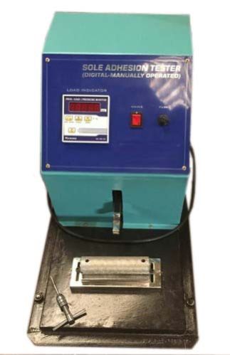
The strength of adhesion of sole of a shoe to its upper is determined by measuring the force needed to pull off the sole from the upper. A suitable last is placed inside the shoe which is then placed on a straight edge acting as a fulcrum for applying load on the joint of the sole and upper. The maximum load the sole is able to withstand before coming off is determined and reported as the sole adhesion strength. This test can be carried out either at the heel or at the toe of the shoe.
Sole Adhesion Tester consists of a load cell and digital indicator to indicate the load applied at the junction of the sole and the upper, a lever arrangement to transmit the load exerted on the toe piece to the spring dynamometer, a straight edge fulcrum for resting the shoe on during the test, and a set of interchangeable toe pieces having different curvature.
The load indicator indicate the load applied on the joint directly in kilograms, taking into account the mechanical advantage of the lever transmitting the force from the toe piece to it. The indicator has the facility of peak hold and tare.
There is an screw arrangement to hold the shoe with last and have the arrangement to up and down movement (load application to the shoe) with the help of the motor, gear box, and screw arrangement.
The toe piece are five in number and having different curvature to enable toes and heels of different shapes and sizes to be tested. The length of arc of each toe piece, however, is the same to ensure that the load is applied only on a fixed length of joint. They are made from carbon steel for giving a long operational life. Any one of the toe pieces can be held in the equipment at one time.
The fulcrum on which the shoe is placed during the test has adjustable height to enable soles of different thickness to be tested. The height of the fulcrum is adjusted with the help of spacer strips provided with the instrument.
The instrument is finished in painting and bright chrome plating to give it a corrosion resistant finish.


